

Lets get serial.
Multi-port serial and prototyping card
In a previous post, I briefly discussed a small card with an RS-232 serial port on it. This card was used for interfacing a host computer to our EDDIE system when it was running K4. That idea has been expanded and turned into our first EDDIE peripheral card design.
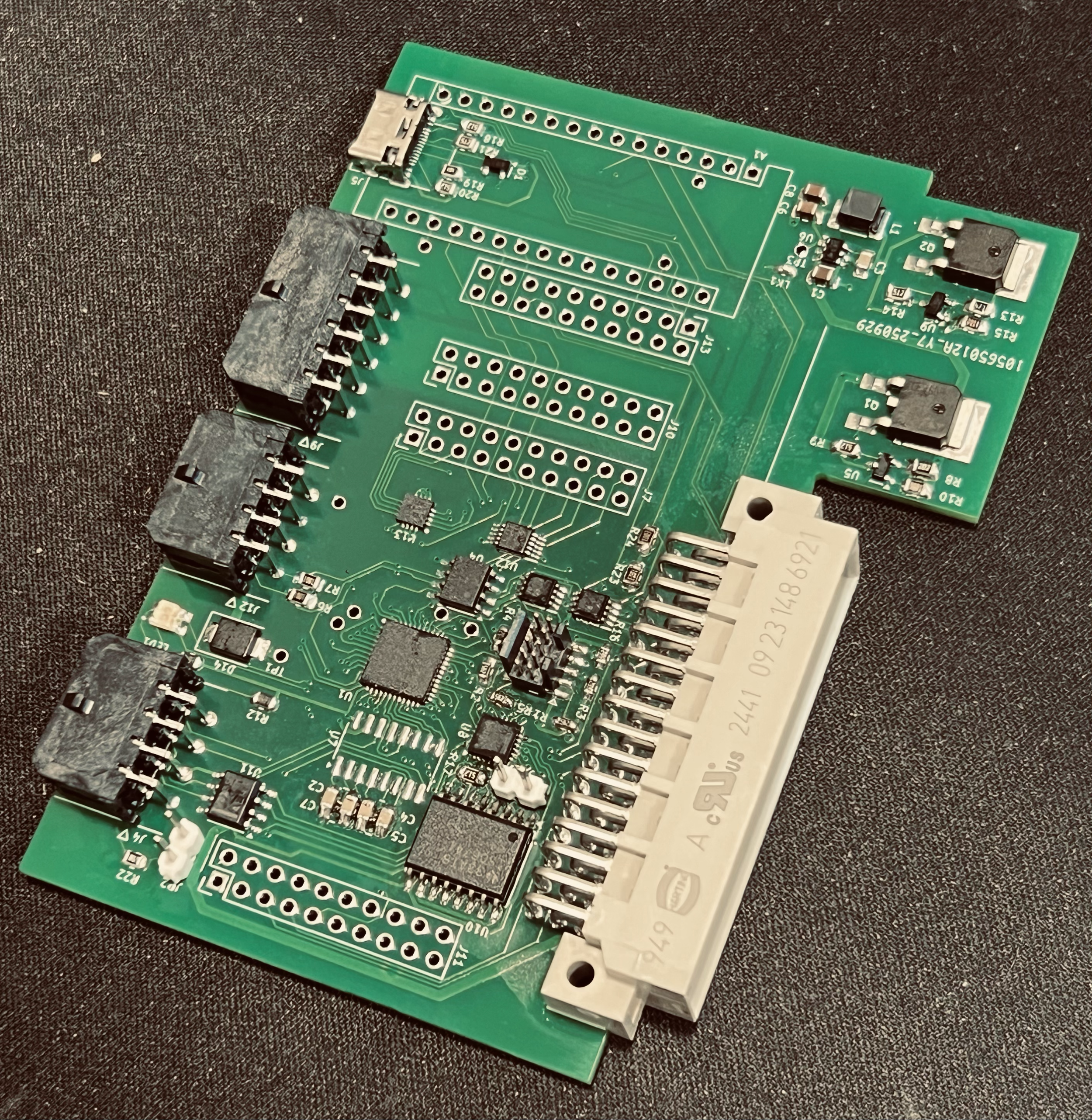
Pictured above is our first hand-assembled serial card.
The block diagram below shows the functions of the serial card. See that the FPGA mostly routes UART signals according to slot control signals from the main bus. A small microcontroller functions to provide a UART port from USB and to decode the analog slot signal to a digital value the FPGA uses for slot selection.

EDDIE Serial Card block diagram
You can see that this card does more than just provide RS-232 conversion for a single UART channel. Certainly, one UART channel is routed through an FPGA to an RS-232 port. More than that though, that same, or another UART channel can be routed to an RS-485 interface.
In fact this new card has lots of nice features:
Two RS-232 serial ports
One RS-485 port.
USB-Serial conversion. Serial port can be routed arbitrarily through the FPGA.
Switching of any of these ports, and the bus UART port through the FPGA to enable many different configurations.
The card has an I2C ADC with four un-committed inputs and a DAC with four un-committed outputs.
The layout of the card makes alteration and prototyping a possibility so that future cards or functionality can be tested on it as a new platform.
This card also helps us test and write software for “Slot control”. This is functionality that allows us to determine what type of card is installed in which backplane slot. To do this requires some circuitry that can report on I2C the card type and its features as well as determine which slot the card is in and report that information.
An ATSAMD11D14A microcontroller is being used on most proposed designs as a “slot” controller.
This device measures the SLOT voltage that is unique to each position on the bus and generates a four bit (sixteen slots) slot code. This can be used by switching or multiplexing devices on each card to determine if they are being addressed by either of the slot address busses (S1Ax and S2Ax).
This functionality is expected to be standard on many EDDIE cards by using this circuit as prototyped on this card.
Probe Ports:
Finally, this card provides a newly conceived “probe” port. These ports include an isolated I2C channel and an isolated CAN channel. If you look back at the CPU51 design blog, you will notice a similar port there. In fact the connector and pinout is the same. These ports are designed to connect to devices called that I will introduce in up-coming posts. The simple concept of a probe is that it is a single (or minimal) unit of I/O that can be physically placed near the point is measuring or controlling. They were conceived so that we can get EDDIE applied to a number of potential projects without building full sized EDDIE cards.
We shall discuss some probes in our next post.