

The first EDDIE System!
To build a our first prototype in a card cage, we needed the backplane card and a power supply. The backplane was simple as it consists of connectors only.
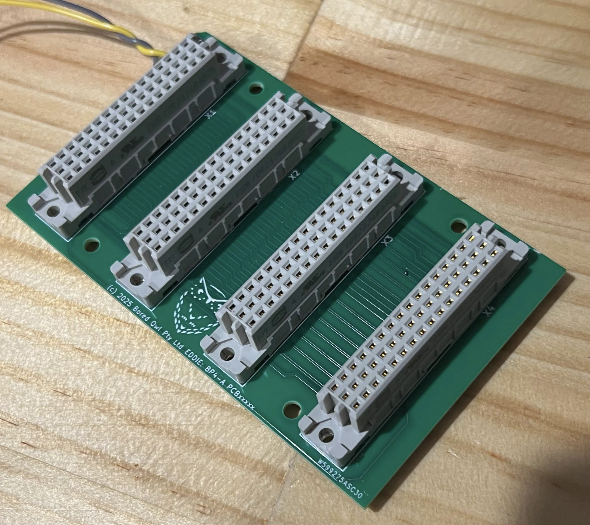
Eddie 4 slot backplane: Revision A
The design of the Ethernet and power card was more elaborate. This card had to include:
A 15W 3.3V power supply for the bus
A five port Ethernet switch model (supplied by a third party). One port of this switch is used internally.
An SPI to Ethernet circuit. The SPI port comes from a special port that is built into CPU cards that support Ethernet capability
We used pre-built modules for the power supply, Ethernet switch and RJ45 jacks with their magnetic components. The remainder of the board - the power input/protection circuits and the SPI-Ethernet conversion is made with discrete components. This board slightly exceeded 100mm wide so it was more costly than our original desire. Hopefully it will be reduced in a new revision:
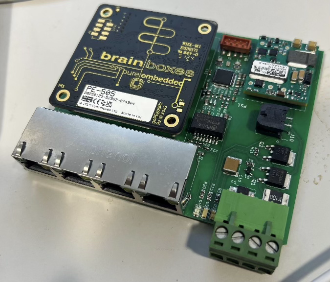
EDDIE Etherpower card. Revision A
The first CPU card is much more of a technical challenge. The features of the card were desired to be:ARM Cortex-M4+ CPU. We nominated the Atmel ATSAMD51 device as it has sufficient I/O to support on-card requirements and the bus system.
Ability to switch and configure the CPU ports onto the bus so that the card can both control (as master) or listen (as a peripheral) to the various bus channels.
Include 24V PLC grade digital I/O ports galvanically isolated from the CPU logic.
Include a 915Mhz radio module for LoRA applications.
Include a USB port for host configuration and communication.
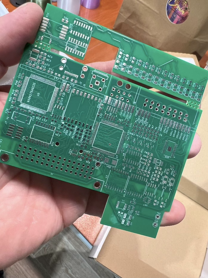
It took numerous iterations to determine how to fit all the required features onto the card. An FPGA was also employed to reduce the component count, give us flexibility in routing the PCB and increase the available features.
The final iteration also broke our constraint about PCB cost. The PCB requires six layers (instead of two normally employed in prototypes). That’s four signal layers and two power planes to get all the signals routed. The result is a quite compact design:
The design achieved a lot of feature:
ATSAMD51D20A CPU and FPGA with 256 LUT logic capability. This is clocked at up to 120Mhz, has 1MB Flash and 256K RAM
915MHz radio module
USB-C Connection
Dual SPI bus channels, dual I2C bus channels
CANbus and I2C on bus and front I/O. Isolated.
Six digital inputs with programmable voltage thresholds up to 24VDC, Four 24VDC high side digital outputs and four 24VDC low side digital outputs
SD Card
Ethernet SPI support
Seven segment status indicator with LED indicators on all inputs and outputs.
8Mbit QSPI Flash for code and data
We are very excited about the capabilities of this CPU card. It has been designed as a roughly mid-range processor with plenty of features.
So where does this collection of cards bring us?
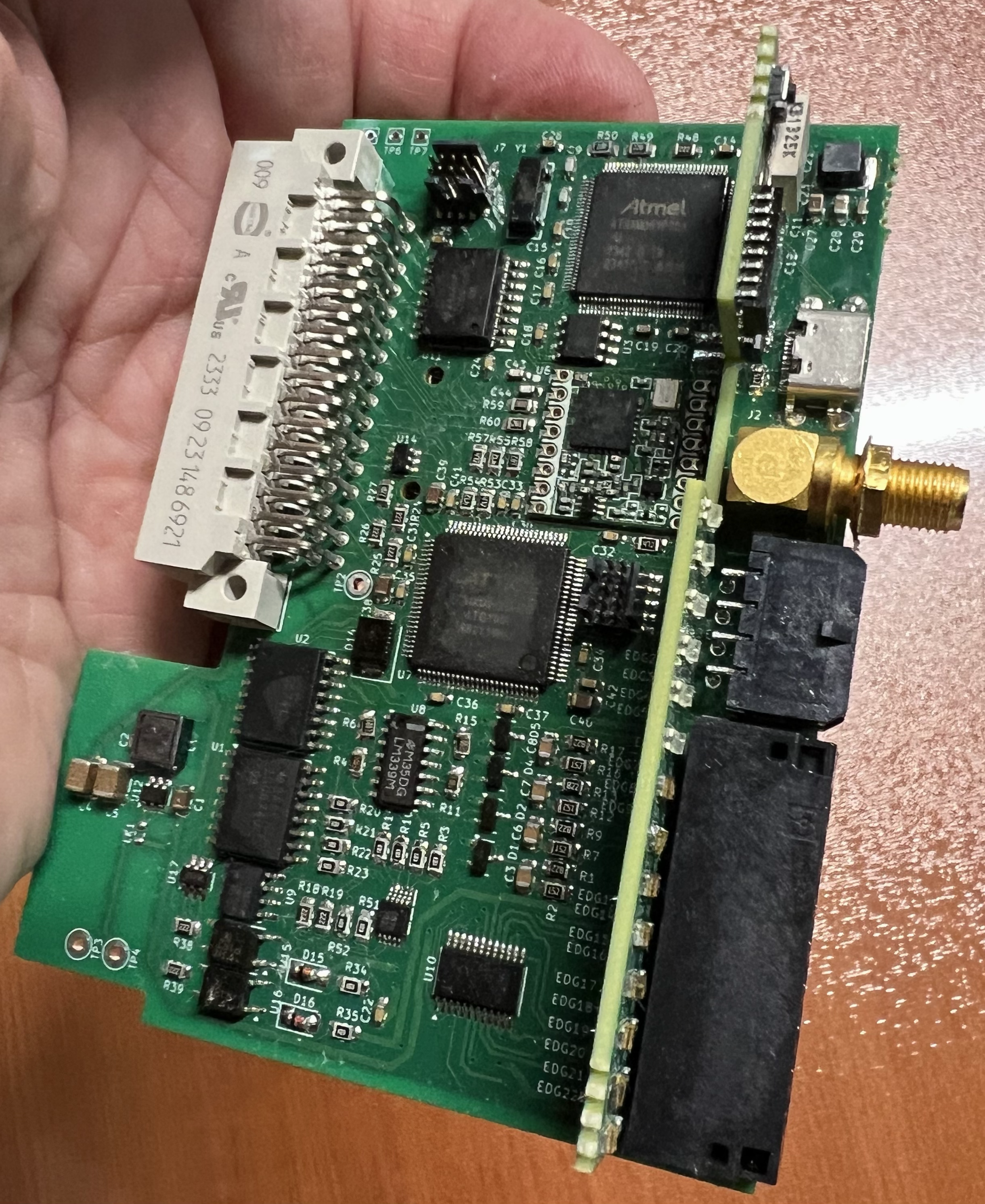
Putting together the three cards that are the basis for a basic EDDIE system has been our focus in the past few months. The test system is now set up in a test frame as shown in the picture below.
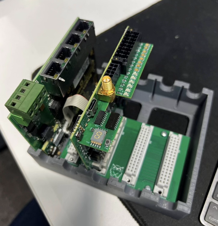
This system is powered up and will be undergoing tests in the coming months.
Certainly at the end of that time, there will be a design iteration process. Our goal in the cycle is to proove the processor and I/O circuitry and to have a prototype of a basic operating system running over a console connection.
The CPU card on its own does not have many sources of data - only the digital I/O ports. Until we build peripheral cards, analog measurements (voltage, temperature current etc) are not available.
That said, we are aiming to use the basic operating system to record inputs onto the SD card and control outputs (based on some simple arbitrary logic). This will form the basis for the first “application” - an automated test rig. If you want to speed up on the operating system, hop over to the “K4” blog. There we talk about a language and command line system for building applucations on these EDDIE boards.
In our next post, we’ll get a bit more technical and talk about the actual system architecture and start testing our system out.
Features and functions described in our blog posts are not final specifications. Products when made for sale will be published with official documentation and specifiactions that may differ from our aspirations during this development process.